Printhead‑to‑product distance, also commonly referred to as printing stand‑off distance in the industry, specifically means the vertical clearance between the printhead nozzle face and the surface of the target product. It is a core height parameter for piezoelectric industrial inkjet and UV on‑line coding systems.
The printhead height cannot be set arbitrarily. After ink droplets are ejected from nozzles, they follow a flight path. Variations in this distance directly affect ink droplet landing position, spread range and print formation quality.
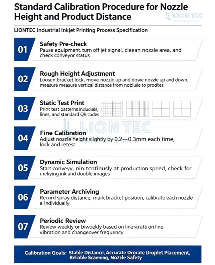
Standard Procedure for Printhead Distance Calibration
Step 1: Pre‑calibration Safety Inspection & Environment Verification
Pause equipment operation and disable printhead firing signals. Confirm target products are positioned at the normal printing station on the production line. Check that the conveyor belt has no obvious shaking or height fluctuation. Inspect the printhead nozzle face for dried ink residue; gently clean nozzles when necessary to avoid nozzle clogging which distorts test results.
Step 2: Coarse Mechanical Adjustment of Printhead Vertical Height
Loosen the printhead bracket locking knob and move the full printhead assembly vertically. Use a scale to measure the vertical clearance from the lowest nozzle face to the product surface. Adjust to the reference distance specified for the printhead model, then temporarily tighten the bracket screws.
Note: Take measurements directly below the nozzles to prevent data errors caused by angled measurement.
Step 3: Static Printing of Test Patterns
Enable dry‑run printing. Print standard test patterns on sample surfaces. Recommended patterns include grid blocks, horizontal‑vertical lines and combined standard QR‑codes. Print 5‑10 consecutive sample sets. Visually inspect character edges and dot‑matrix uniformity for one‑direction stretching or left‑right offset.
Step 4: Fine Height Tuning & Re‑measurement
If printed characters appear scattered or QR‑codes are distorted, slightly lower the printhead height. If ink splash dots or local ink accumulation occur, slightly raise the printhead. Each adjustment shall be within 0.2‑0.3 mm. Tighten the bracket after adjustment and print again for comparison. Repeat iterations until stable pattern output is achieved.
Step 5: Dynamic Production‑Line Simulation Calibration
Start the conveyor belt and run continuous printing at normal production speed. Closely observe whether vertical product bounce creates stand‑off distance variation as products pass under the printhead. For production lines with heavy vibration, apply an increased safety distance margin.
Step 6: Parameter Archiving & Position Marking
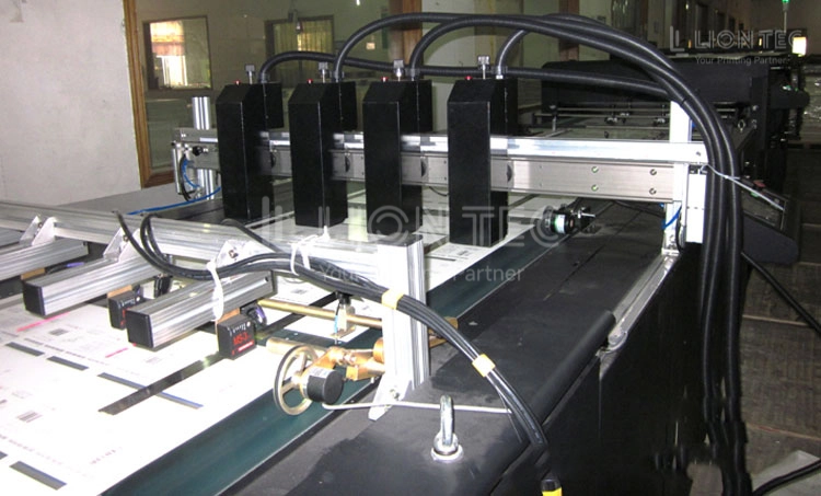
After successful calibration, mark the adjusted position on the mounting bracket. Record current stand‑off distance parameters in the control system for quick position recall during future product change‑overs. For multi‑printhead array systems, calibrate each printhead individually to ensure uniform stand‑off distance across all units.
Step 7: Routine Periodic Re‑verification Standard
Printhead distance re‑verification is recommended every two weeks. For workshops with heavy line vibration or frequent material change‑overs, perform calibration checks on a weekly basis.
Advantages of Stand‑off Distance Calibration
1. Stabilize printing quality and reduce defective products
Consistent stand‑off distance keeps ink droplets flying under stable conditions, delivering uniform fonts, barcodes and QR‑codes. It minimizes marking defects such as ghosting, stretching and partial ink dropout, cutting rework costs for quality inspection. It also meets high‑standard marking requirements including UDI traceability and product anti‑counterfeiting codes.
2. Extend service life of piezoelectric printheads and lower component wear
Precise calibration maintains a safe clearance to prevent workpiece scuffing against the printhead. It also suppresses excessive ink mist buildup on nozzles, reduces frequent cleaning cycles, slows nozzle clogging, and controls printhead replacement expenses.
3. Compatible with high‑speed production lines for improved line flexibility
With standardized distance parameters, commissioning time is greatly shortened during line‑speed increases and material change‑overs. Downtime for adjustment is reduced, which raises the overall availability of the automated production line.
4. Cut ink waste and improve workshop working conditions
Improper stand‑off distance causes overspray and scattered ink, which contaminate products and conveyor belts. Standard calibration greatly reduces ink mist, lowers ink consumption and eases routine equipment‑cleaning workload.
Conclusion
LIONTEC specializes in the R&D and manufacturing of industrial piezoelectric inkjet and inline UV coding systems. We deliver complete printing process solutions for pharmaceutical UDI, electronics, packaging, pipe‑materials and other industries.
If you require recommended stand‑off distance parameters or on‑site process commissioning support tailored to your production‑line printhead model, please contact our technical engineers.