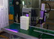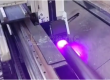
The full‑performance output of an Industrial UV Marking Printer largely depends on standardized electrical connection and precise signal synchronization settings. Electrical connection and signal synchronization serve as the cornerstone for stable operation of the device. The former addresses how to complete wiring connection, while the latter solves how to achieve accurate marking.
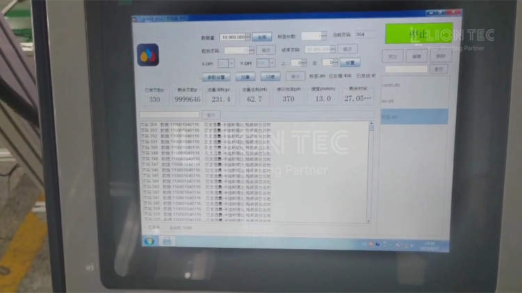
UV Coder Electrical Connection and Signal Synchronization
I. On‑site Condition Survey and Accessory Verification
- Record production‑line parameters: maximum line running speed, roller diameter, product pitch, and existing production‑line control system (with or without PLC).
- Verify accessories: main unit of the Industrial UV Marking Printer, printhead module, UV curing lamp, photoelectric sensor / encoder, double‑layer shielded signal cable, and earthing cable. Confirm the sensor output type (NPN/PNP) matches the IO port specification of the marking printer.
II. Main‑unit Power‑supply Circuit & Protective Earthing Wiring
- Connect the main unit of the Industrial UV Marking Printer and UV curing unit to a stable industrial power supply respectively. Voltage shall comply with nameplate requirements. Do not share one circuit with high‑power motors.
- Apply independent protective earthing for the equipment enclosure. Do not share earthing busbars with frequency converters or welding machines to eliminate interference caused by voltage difference.
- Connect the printhead module to the main unit with original‑manufacturer dedicated flat cables and lock the connectors tightly to avoid poor contact induced by production‑line vibration.
III. IO Electrical Wiring for External Trigger Components
- Photoelectric sensor: connect power cable to 24 V power supply; feed signal‑output cable into the IN trigger port of the marking printer.
- Encoder: route A/B‑phase pulse signals to the encoder port on main unit via shielded cable with single‑end shielding earthing. Mount the encoder mechanically on the driving roller and ensure zero slippage of driving wheels.
- For production‑line PLC integration: feed PLC start‑stop signals and fault‑feedback signals to IO input & output terminals of the Industrial UV Marking Printer to build bidirectional signal links.
- Wiring requirement: keep signal cables away from power cables of motors and frequency converters. Do not lay signal wires together with power wires inside one cable duct to reduce electromagnetic interference.
IV. Basic Synchronization‑parameter Configuration on Software Side
- Log in to the marking‑printing system, create a new printing template, and set printing content and resolution.
- Select trigger mode according to external hardware: choose Photoelectric Trigger for standalone photoelectric‑sensor setup; select Encoder + Photoelectric Trigger for production lines fitted with encoders.
- Input the circumference of the encoder‑driven roller and perform pulse calibration, so that the equipment can calculate the actual moving distance of the production line.
- Set signal‑edge mode (rising‑edge / falling‑edge). Enable signal de‑bounce to filter mis‑triggering caused by noise in workshop environment.
V. Trial‑run Commissioning & Synchronization‑parameter Optimization
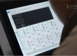
- Run the production line with no load. Monitor the system UI and confirm encoder pulses and photoelectric trigger signals are read normally without signal loss.
- Load real production samples. Fine‑tune printing‑trigger delay parameters to shift printed marks to target positions on products.
- Alternate production‑line operation between low speed and rated high speed. Observe printing‑position stability. Fine‑tune motion‑compensation parameters in case of position offset.
- Continuously print 20‑50 samples. Confirm printing‑position deviation stays within process‑allowed tolerance, and QR‑code / barcode reading rate meets specifications.
VI. Cable Fastening, Parameter Saving & Document Archiving
- After full commissioning passes, tighten all wiring terminals. Fasten and protect cables against pulling and abrasion on production lines.
- Save the full set of synchronization parameters as a product configuration file for quick recall during product‑switchover. Document wiring schemes and parameters for later maintenance and fault troubleshooting.
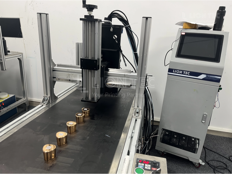
Core Advantages of Connection and Synchronization for Industrial UV Marking Printer
- Reduce Defective‑product Waste When signal synchronization of the Industrial UV Marking Printer is properly commissioned, printing offset, missing prints, duplicate prints, QR‑code recognition failures and other defects can be greatly minimized, lowering rework and scrap rates. It delivers particular value for UDI medical‑device and one‑item‑one‑code traceability production lines.
- Support Variable‑speed Production on Production Lines Print positions stay stable during line acceleration, deceleration, start‑up and shutdown. There is no need for repeated manual adjustment of marking parameters, which enables line change‑over for multi‑specification products.
- Extend Service Life of Electrical Control Components Standardized electrical wiring, earthing and shielded cabling reduce impacts from surge voltage and electromagnetic interference on control boards and printheads of the Industrial UV Marking Printer. It decreases random error alerts and main‑board failure risks, extending the overall equipment lifespan.
- Realize Automated Closed‑loop Production With correct IO electrical docking completed, the Industrial UV Marking Printer exchanges start‑stop and fault‑alarm signals with the production‑line PLC. It connects to MES systems to receive variable printing data, achieving fully‑automatic unattended inline coding and integration into factory‑automation frameworks.
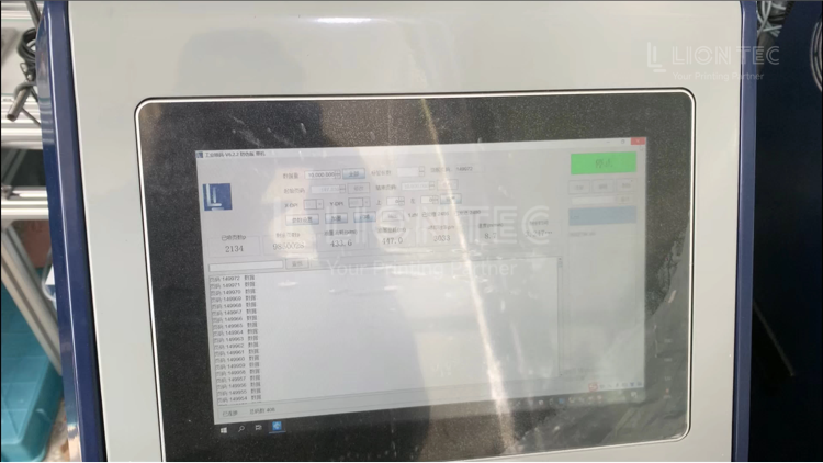
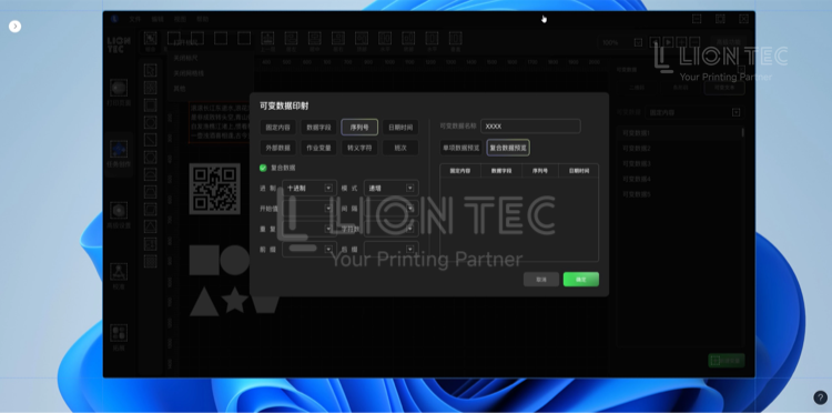
Conclusion
The electrical connection and signal‑synchronization settings for the Industrial UV Marking Printer may seem like basic steps in equipment installation and commissioning. In fact, they are critical factors that determine printing accuracy, equipment stability and production‑line efficiency. Standardized electrical connections deliver reliable physical channels for signal transmission, while precise signal‑synchronization configurations provide algorithm‑driven guarantees for printing accuracy.