This article covers Coding Position Offset of UV Inkjet Printers — one of the most common issues during UV inkjet printers operation. Characters may shift forward, backward or float vertically — in mild cases this affects product appearance consistency, and in severe cases it causes QR codes to become unrecognizable and traceability information to fail.
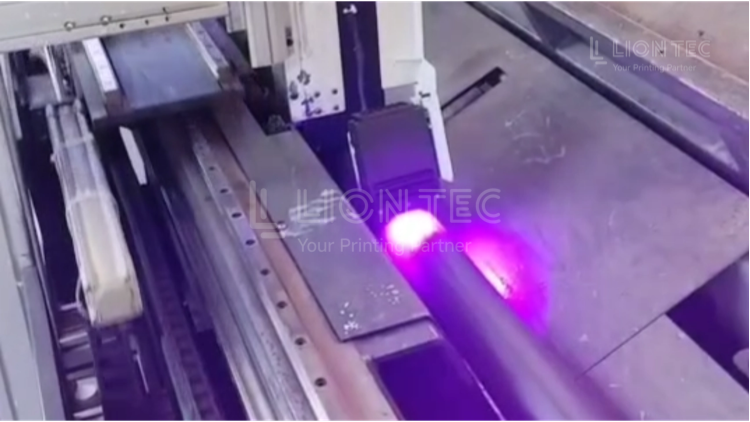
Position Offset Calibration
I. Conduct Comprehensive Mechanical and Hardware Inspection After Shutdown
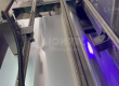
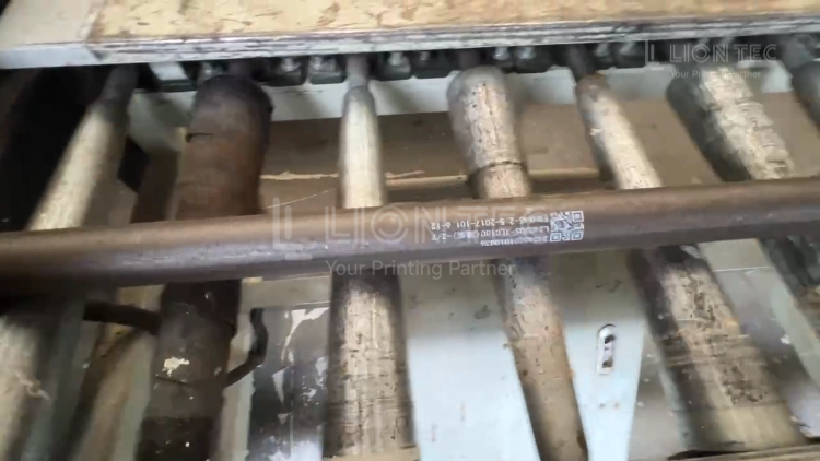
- Inspect the printhead bracket: tighten all fixing screws on the printhead, confirm that the bottom surface of the printhead is as perpendicular as possible to the product printing surface. Use a feeler gauge to verify the distance from the printhead to the substrate, and fine-tune according to material thickness to ensure the material passes through without scraping the printhead.
- Inspect the photoelectric trigger sensor: measure and record the horizontal distance between the sensor trigger point and the center of the printhead. Mount the sensor slightly lower than the printhead to ensure stable trigger signals for every product. Tighten the fixing bracket screws firmly to eliminate vibration-induced displacement.
- Inspect the encoder: press the encoder roller firmly and confirm it rotates synchronously with the production line without slipping. Use shielded cable for wiring, keep it away from high-power equipment such as VFDs, and ensure proper equipment grounding.
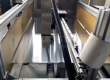
- Inspect the conveyor line: install product limit guides to eliminate lateral material movement. Confirm that the line speed remains stable during operation without sudden acceleration or deceleration.
II. Print Multiple Test Samples and Determine Offset Direction and Magnitude
- Start the production line and continuously print more than 10 real products to observe the coding offset.
- Front-back offset: this is a print delay parameter issue.
- Left-right offset: this is an X-axis offset compensation / printhead mounting position issue. Use a marked ruler to measure the millimeter-level deviation between the actual print position and the standard target position, and record the offset direction and value.
III. Targeted Software Parameter Fine-Tuning
- Front-back offset: enter the system print trigger settings and adjust the start delay parameter. If the code is shifted forward, increase the delay; if shifted backward, decrease the delay. Make small adjustments each time rather than large changes at once, and print a few samples to observe the effect after each adjustment.
- Left-right offset: first coarsely adjust by mechanically moving the printhead bracket. For fine deviations, modify the X-axis offset compensation value in the software for small corrections.
- If multiple lines of content are vertically misaligned, fine-tune the Y-axis offset compensation.
- After modifying parameters, always save the parameter profile for easy recall when working conditions change later.
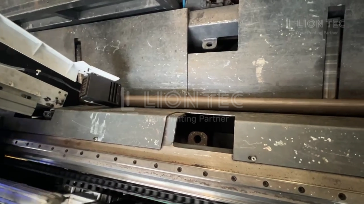
IV. Verify Batch Stability and Rule Out Occasional Drift
- After parameter adjustment, run multiple products consecutively and inspect samples to confirm that the position is consistent across the entire batch, not just a single lucky sample.
- If samples drift left and right or front and back intermittently, stop adjusting software parameters and return to Step 1 to re-inspect for mechanical looseness, signal interference or material jumping.
V. Recalibration After Working Condition Changes
- After changing product specifications, altering line speed, or removing and reinstalling the printhead bracket, re-run the entire calibration process. Old parameters cannot be directly reused under new working conditions.
Advantages of Offset Calibration
1. Reduce production defect losses
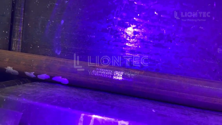
Codes printed outside the target area cause large batches of product scrap and rework. With proper calibration, QR codes, traceability codes and production dates all land at the designated printing position, reducing scrap, rework labor and material losses — especially suitable for high-value packaging and component coding production.
2. Ensure stable barcode scanning recognition
QR codes and UDI codes have very small tolerance for printing position deviation. Excessive offset renders them unrecognizable by scanners. After proper calibration, position consistency within a batch is high, scan grades remain stable, and the risk of scanning failure in downstream logistics is avoided.
3. Reduce repeated commissioning and downtime
Once the complete hardware and parameter calibration is done, production can run stably for long periods under unchanged line conditions, without repeated mid-production shutdowns to fine-tune print position, improving line uptime.
4. Extend printhead service life
Calibration synchronizes printhead height and angle, maintaining a safe distance between the printhead and substrate and preventing material from scraping the nozzle surface, reducing physical damage to the printhead and lowering spare part replacement costs.
Conclusion
When offset recurs repeatedly and cannot be resolved after inspecting mechanical and signal factors, contact the manufacturer’s technical team for remote or on-site diagnosis of printhead hardware and control system faults. It is recommended to establish an equipment maintenance ledger, recording line speed, printhead height and delay offset parameters for each calibration, to facilitate rapid commissioning in the future.