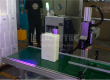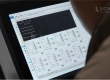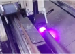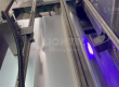
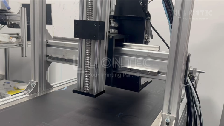
The mechanical‑installation quality of Industrial UV Marking System directly determines whether the equipment can run stably for a long time after commissioning and whether printing accuracy can meet design specifications. As an engineering project involving precise mechanical transmission and multi‑module coordination, bracket / slide‑rail fixing and printhead positioning are the two most critical procedures in mechanical installation.
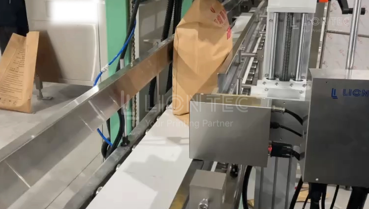
Slide‑Rail Fixing + Printhead Positioning
Note: The following is the standard installation procedure for LIONTEC Industrial UV Marking System.
1. Survey and Clean‑up of Installation Base Surface Before Installation
Confirm that the mounting position of the production‑line frame is flat and free of deformation. Check the levelness of the reference surface with a level gauge. Remove welding slag, burrs and dust from the frame surface. Select bracket mounting points away from strong vibration sources such as conveyor motors and rollers.
2. Pre‑assembly and Initial Positioning of Bracket Base
Place the main support bracket onto the preset mounting points. Hand‑tighten all fixing bolts without fully locking them. Adjust the bracket height preliminarily, and reserve safe moving clearances for the slide‑rail carriage, printhead and UV lamp.
3. Reference Installation and Parallelism Calibration of Slide Rails
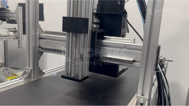
- Place the reference‑side linear slide rail onto the reference step of the bracket crossbeam.
- Inspect the levelness and straightness of slide rails by using a level gauge and dial indicator.
- Adjust the driven‑side slide rail with the reference slide rail as benchmark to ensure parallelism between the two slide rails.
- Tighten slide‑rail fixing screws diagonally in multiple passes according to the torque recommended in the equipment manual, and install shock‑absorbing gaskets.
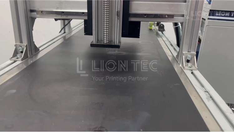
- Manually push the slider carriage to slide through the full stroke. Qualified status means smooth travel without jamming or fluctuating resistance.
4. Mount Printhead Module for Rough Mechanical Positioning
Install the printhead fixing block onto the slider of the slide‑rail carriage, and fasten printhead locking screws. According to production‑line flow direction, roughly adjust the 3‑dimensional position of the printhead along X(left‑right), Y(front‑back) and Z(height) axes. Keep printhead nozzles facing the conveyor surface and perpendicular to it.
5. Fine‑tuning for Precise Printhead Positioning
- Z‑axis height: Adjust the printing gap between printhead and substrate. The default recommended gap for UV industrial inkjet is 10‑15 mm.
- X‑Y horizontal direction: Align with the reference line of the printing area.
- Angle verification: Confirm no left‑right tilt of the printhead by using a try square.
- Printhead locking: After all positions are confirmed, tighten bolts of the printhead fixing block sequentially.
6. No‑load Vibration Recheck Test
Run the production line under no‑load condition for 30 minutes to subject brackets and slide rails to normal production‑line vibration. Stop the line and re‑check bracket screw torque, slide‑rail parallelism and printhead position for offset. Re‑reinforce components if any offset occurs.
7. Test Printing & Secondary Software Calibration
Place standard test substrate for test printing. Compare the position of printed patterns. Minor deviations can be compensated via X/Y offset adjustment within the inkjet control system to complete closed‑loop acceptance for final printhead positioning.
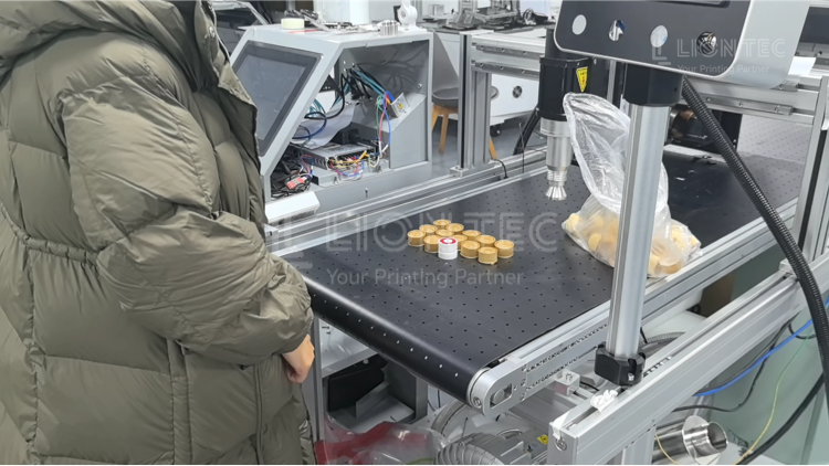
Advantages of Standardized Installation
1.Long‑term stable printing accuracy and reduced position‑drift failures.
A rigid bracket and slide‑rail base offsets mechanical displacement caused by production‑line vibration. The printhead positioning accuracy of the Industrial UV Marking System can be stably maintained within ±0.1‑0.3 mm. During high‑volume continuous production, identification patterns and traceability barcodes will not gradually shift, lowering scrap rates.
2.Extended service life of printhead and slide‑rail components.
Qualified slide‑rail parallelism and even printhead load deliver balanced travel resistance for the carriage and reduce slider wear. Free from long‑term stress tension, the printhead lowers risks of nozzle deformation and ink leakage, and reduces subsequent maintenance frequency.
3.Better production‑line compatibility and higher debugging efficiency for product change‑overs.
Once the standardized bracket‑printhead positioning reference is established, only minor parameter adjustments are required for subsequent product‑switching and printing‑content modification. No extensive mechanical disassembly is needed, which greatly shortens change‑over debugging time.
4.Avoid high troubleshooting costs for complex later‑stage failures.
Resolve mechanical‑precision issues at the installation phase. When printing misalignment occurs later, hardware‑installation factors can be ruled out directly. You can quickly target encoders, photoelectric signals, software synchronization and other aspects, significantly cutting fault‑diagnosis time.
Conclusion
If you want to learn more technical details about installation and commissioning for industrial inkjet equipment, please feel free to contact the LIONTEC technical team.